BS 10 Plate Flange & Blind Flange Dimensions (Tables D, E, F, H)
This chart gives BS 10 plate flange and blind flange dimensions in millimetres for Tables D, E, F and H — outside diameter, bore, plate and blind thickness, and drilling. BS 10 is withdrawn but its Table D, E, F and H drilling is still widely used on existing plant and marine equipment.
Plate flanges are Teshi Group's core product: cut, machined and drilled in our own works in India from DN 10 up to 8000 NB (8 metres), in carbon, boiler-quality, stainless, duplex and nickel-alloy plate, with EN 10204 3.1 certificates.
Key to dimensions
- D
- Outside diameter of flange
- B
- Bore (inside diameter) of plate flange
- C
- Flange thickness — plate or blind, raised face (RF) or flat face (FF)
- K
- Bolt circle (pitch circle) diameter
- n
- Number of bolt holes
BS 10 Plate Flange & Blind Flange Dimensions (Tables D, E, F, H) — tables
BS 10 Table D — plate and blind flange (mm)
| SizeNB | DFlange OD · mm | BBore · mm | CPlate, RF · mm | CPlate, FF · mm | CBlind, RF · mm | CBlind, FF · mm | KBolt circle · mm | nBolts | BoltDia · mm |
|---|---|---|---|---|---|---|---|---|---|
| 15 | 95.3 | 23.3 | 4.8 | 4.8 | 4.8 | 4.8 | 66.7 | 4 | 12.7 |
| 20 | 101.6 | 28.7 | 4.8 | 4.8 | 4.8 | 4.8 | 73 | 4 | 12.7 |
| 25 | 114.3 | 35.4 | 4.8 | 4.8 | 4.8 | 4.8 | 82.6 | 4 | 12.7 |
| 32 | 120.7 | 44.2 | 6.4 | 6.4 | 6.4 | 6.4 | 87.3 | 4 | 12.7 |
| 40 | 133.4 | 50.3 | 6.4 | 6.4 | 6.4 | 6.4 | 98.4 | 4 | 12.7 |
| 50 | 152.4 | 62.3 | 7.9 | 7.9 | 7.9 | 7.9 | 114.3 | 4 | 15.9 |
| 65 | 165.1 | 75 | 7.9 | 7.9 | 7.9 | 7.9 | 127 | 4 | 15.9 |
| 80 | 184.2 | 90.9 | 9.5 | 9.5 | 9.5 | 9.5 | 146.1 | 4 | 15.9 |
| 90 | 203.2 | 103.6 | 9.5 | 9.5 | 9.5 | 9.5 | 165.1 | 4 | 15.9 |
| 100 | 215.9 | 116.3 | 9.5 | 9.5 | 9.5 | 9.5 | 177.8 | 4 | 15.9 |
| 125 | 254 | 143.3 | 12.7 | 12.7 | 12.7 | 12.7 | 209.6 | 8 | 15.9 |
| 150 | 279.4 | 170.3 | 12.7 | 12.7 | 12.7 | 12.7 | 228.6 | 8 | 15.9 |
| 175 | 304.8 | 192.5 | 12.7 | 12.7 | 12.7 | 12.7 | 260.4 | 8 | 15.9 |
| 200 | 336.6 | 221.1 | 12.7 | 12.7 | 12.7 | 12.7 | 292.1 | 8 | 15.9 |
| 225 | 368.3 | 246.5 | 15.9 | 15.9 | 15.9 | 15.9 | 323.9 | 8 | 15.9 |
| 250 | 406.4 | 275 | 15.9 | 15.9 | 15.9 | 15.9 | 355.6 | 8 | 19.1 |
| 300 | 457.2 | 325.9 | 15.9 | 19.1 | 15.9 | 19.1 | 406.4 | 12 | 19.1 |
| 350 | 527.1 | 357.6 | 19.1 | 22.2 | 19.1 | 22.2 | 469.9 | 12 | 22.2 |
| 400 | 577.9 | 408.4 | 19.1 | 22.2 | 19.1 | 22.2 | 520.7 | 12 | 22.2 |
| 450 | 641.4 | 459.2 | 22.2 | 25.4 | 22.2 | 25.4 | 584.2 | 12 | 22.2 |
| 500 | 704.9 | 510 | 25.4 | 28.6 | 25.4 | 28.6 | 641.4 | 16 | 22.2 |
| 600 | 825.5 | 611.6 | 28.6 | 31.8 | 28.6 | 31.8 | 755.7 | 16 | 25.4 |
BS 10 Table E — plate and blind flange (mm)
| SizeNB | DFlange OD · mm | BBore · mm | CPlate, RF · mm | CBlind, RF · mm | KBolt circle · mm | nBolts | BoltDia · mm |
|---|---|---|---|---|---|---|---|
| 15 | 95.3 | 23.3 | 6.4 | 6.4 | 66.7 | 4 | 12.7 |
| 20 | 101.6 | 28.7 | 6.4 | 6.4 | 73 | 4 | 12.7 |
| 25 | 114.3 | 35.4 | 7.1 | 7.1 | 82.6 | 4 | 12.7 |
| 32 | 120.7 | 44.2 | 7.9 | 7.9 | 87.3 | 4 | 12.7 |
| 40 | 133.4 | 50.3 | 8.7 | 8.7 | 98.4 | 4 | 12.7 |
| 50 | 152.4 | 62.3 | 9.5 | 9.5 | 114.3 | 4 | 15.9 |
| 65 | 165.1 | 75 | 10.3 | 10.3 | 127 | 4 | 15.9 |
| 80 | 184.2 | 90.9 | 11.1 | 11.1 | 146.1 | 4 | 15.9 |
| 90 | 203.2 | 103.6 | 11.9 | 11.9 | — | — | — |
| 100 | 215.9 | 116.3 | 12.7 | 12.7 | 177.8 | 8 | 15.9 |
| 125 | 254 | 143.3 | 14.3 | 14.3 | 209.6 | 8 | 15.9 |
| 150 | 279.4 | 170.3 | 17.5 | 17.5 | 228.6 | 8 | 19.1 |
| 175 | 304.8 | 192.5 | 19.1 | 19.1 | — | — | — |
| 200 | 336.6 | 221.1 | 19.1 | 19.1 | 292.1 | 8 | 19.1 |
| 225 | 368.3 | 246.5 | 20.6 | 20.6 | — | — | — |
| 250 | 406.4 | 275 | 22.2 | 22.2 | 355.6 | 12 | 19.1 |
| 300 | 457.2 | 325.9 | 25.4 | 25.4 | 406.4 | 12 | 22.2 |
| 350 | 527.1 | 357.6 | 25.4 | 25.4 | 469.9 | 12 | 22.2 |
| 400 | 577.9 | 408.4 | 25.4 | 25.4 | 520.7 | 12 | 22.2 |
| 450 | 641.4 | 459.2 | 28.6 | 28.6 | 584.2 | 16 | 22.2 |
| 500 | 704.9 | 510 | 31.8 | 31.8 | — | 16 | 22.2 |
| 600 | 825.5 | 611.6 | 38.1 | 38.1 | 755.7 | 16 | — |
BS 10 Table F — plate and blind flange (mm)
| SizeNB | DFlange OD · mm | BBore · mm | CPlate, RF · mm | CBlind, RF · mm |
|---|---|---|---|---|
| 15 | 95.3 | 23.3 | 9.5 | 9.5 |
| 20 | 101.6 | 28.7 | 9.5 | 9.5 |
| 25 | 120.7 | 35.4 | 9.5 | 9.5 |
| 32 | 133.4 | 44.2 | 12.7 | 12.7 |
| 40 | 139.7 | 50.3 | 12.7 | 12.7 |
| 50 | 165.1 | 62.3 | 15.9 | 15.9 |
| 65 | 184.2 | 75 | 15.9 | 15.9 |
| 80 | 203.2 | 90.9 | 15.9 | 15.9 |
| 90 | 215.9 | 103.6 | 19.1 | 19.1 |
| 100 | 228.6 | 116.3 | 19.1 | 19.1 |
| 125 | 279.4 | 143.3 | 22.2 | 22.2 |
| 150 | 304.8 | 170.3 | 22.2 | 22.2 |
| 175 | 336.6 | 192.5 | 22.2 | 22.2 |
| 200 | 368.3 | 221.1 | 25.4 | 25.4 |
| 225 | 406.4 | 246.5 | 25.4 | 25.4 |
| 250 | 431.8 | 275 | 25.4 | 25.4 |
| 300 | 489 | 325.9 | 28.6 | 28.6 |
| 350 | 552.5 | 357.6 | 31.8 | 31.8 |
| 400 | 609.6 | 408.4 | 31.8 | 31.8 |
| 450 | 673.1 | 459.2 | 34.9 | 34.9 |
| 500 | 736.6 | 510 | 38.1 | 38.1 |
| 600 | 850.9 | 611.6 | 41.3 | 41.3 |
BS 10 Table H — plate and blind flange (mm)
| SizeNB | DFlange OD · mm | BBore · mm | CPlate, RF · mm | CBlind, RF · mm | KBolt circle · mm | nBolts | BoltDia · mm |
|---|---|---|---|---|---|---|---|
| 15 | 114.3 | 23.3 | 12.7 | 12.7 | 82.6 | 4 | 15.9 |
| 20 | 114.3 | 28.7 | 12.7 | 12.7 | 82.6 | 4 | 15.9 |
| 25 | 120.7 | 35.4 | 14.3 | 14.3 | 87.3 | 4 | 15.9 |
| 32 | 133.4 | 44.2 | 17.5 | 17.5 | 98.4 | 4 | 15.9 |
| 40 | 139.7 | 50.3 | 17.5 | 17.5 | 104.8 | 4 | 15.9 |
| 50 | 165.1 | 62.3 | 19.1 | 19.1 | 127 | 4 | 15.9 |
| 65 | 184.2 | 75 | 19.1 | 19.1 | 146.1 | 8 | 15.9 |
| 80 | 203.2 | 90.9 | 22.2 | 22.2 | 165.1 | 8 | 15.9 |
| 90 | 215.9 | 103.6 | 22.2 | 22.2 | — | — | — |
| 100 | 228.6 | 116.3 | 25.4 | 25.4 | 190.5 | 8 | 15.9 |
| 125 | 279.4 | 143.3 | 28.6 | 28.6 | 235 | 8 | 19.1 |
| 150 | 304.8 | 170.3 | 28.6 | 28.6 | 260.4 | 12 | 19.1 |
| 175 | 336.6 | 192.5 | 31.8 | 31.8 | — | — | — |
| 200 | 368.3 | 221.1 | 31.8 | 31.8 | 323.9 | 12 | 19.1 |
| 225 | 406.4 | 246.5 | 34.9 | 34.9 | — | — | — |
| 250 | 431.8 | 275 | 34.9 | 34.9 | 381 | 12 | 22.2 |
| 300 | 489 | 325.9 | 38.1 | 38.1 | 438.2 | 16 | 22.2 |
| 350 | 552.5 | 357.6 | 41.3 | 41.3 | 495.3 | 16 | 25.4 |
| 400 | 609.6 | 408.4 | 44.5 | 44.5 | 552.5 | 20 | 25.4 |
| 450 | 673.1 | 459.2 | 47.6 | 47.6 | 609.6 | 20 | 28.6 |
| 500 | 736.6 | 510 | 50.8 | 50.8 | 673.1 | 24 | 28.6 |
| 600 | 850.9 | 611.6 | 57.2 | 57.2 | 781.1 | 24 | 31.8 |
Notes
- All dimensions are in millimetres; sizes are nominal bore (NB / DN).
- Plate flange thickness is given for raised-face (RF) and flat-face (FF) flanges; where only RF is shown, the FF thickness is the same.
- Reference values for estimation and checking. Verify against the current edition of the standard and the purchase specification before design, purchase or fabrication.
Reference information compiled from the published standard for convenience. It does not replace the current edition of the governing standard, which takes precedence. Verify critical dimensions and properties before design, purchase or fabrication. Teshi Engineers & Sales Promoters (P) Ltd accepts no liability for errors or omissions.
FAQ
BS 10 Plate Flange & Blind Flange dimensions (Tables D, E, F, H): common questions
Is BS 10 still used?
BS 10 has been withdrawn and replaced by BS EN 1092-1, but Table D, E, F and H flanges are still ordered for replacements on older plant, ships and UK-pattern equipment.
Which BS 10 table is heavier, D or E?
Table E is rated higher than Table D and has heavier flanges and more bolts in the larger sizes; F and H are higher again.
Related products, data sheets and standards
Slip-On Flange
OEM manufacturer
View online · PDFTechnical data sheetBlind Flange
OEM manufacturer
View online · PDFBS 10BS 10 Table D flange dimensions
BS 10 Table D flange dimensions (low pressure (about 100 psi cold)): OD, thickness, PCD, holes and bolts, in inches and mm.
View online · PDFBS 10BS 10 Table E flange dimensions
BS 10 Table E flange dimensions (about 200 psi cold): OD, thickness, PCD, holes and bolts, in inches and mm.
View online · PDFBS 10BS 10 Table F flange dimensions
BS 10 Table F flange dimensions (about 300 psi cold): OD, thickness, PCD, holes and bolts, in inches and mm.
View online · PDF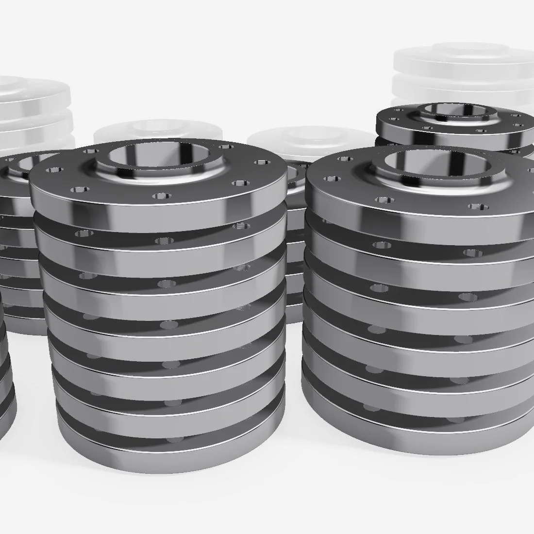
Ready to build to spec?
Share your drawing, bill of materials or technical requirements with the Teshi team.